"Powered" by Textweb
|
voloci | 48V mod | 36V mod | Reflashing the Voloci controller |
Voloci 48 Volt Mod
2009-08-26

DISCLAIMER: THESE INSTRUCTIONS ARE PROVIDED AS-IS. USE AT YOUR OWN RISK. I TAKE NO RESPONSIBILITY FOR DAMAGE, INJURY OR DEATH THAT MAY RESULT.
Seriously -- you can easily fry your Voloci doing this mod. If you do succeed, you will be operating the bike outside its designed parameters, and very likely outside its legal and safe limits. You've been warned. If something bad happens, it's your fault, not mine.
Concept
There are two main complaints I have with my stock Voloci: it doesn't have enough range, and at times it is a bit too slow for blending in traffic on narrow local streets (topping out around 25mph). The bike's native battery runs at 36V, but by running at 48V, the speed should be correspondingly faster. To also increase range, the battery needs more energy capacity.
The stock NiMH battery is rated at 36V and 13Ah, and weighs around 20 pounds, for an energy capacity of approximately 468Wh, and a density of 52Wh/kg. In practice, I have found the NiMH batteries to be a bit inconsistent and I suspect I don't always achieve the rated capacity.


My upgrade uses a new LiFePO4 e-bike battery from pingbattery.com. The battery is rated at 48V and 15Ah, and weighs 7.5kg, for a capacity of 720Wh, and a density of 96Wh/kg. The rated energy density is almost double that of the NiMH pack. Nice! I also read on the web that the LiFePO4 batteries don't mind being run in parallel, so it should be possible to add another battery to further increase the Voloci's range.

Modifying The Voloci For 48V
In practice, the Ping battery puts out 59V when fully charged. The Voloci motor and drivetrain can work with a 59V power source, but the motor controller board was definitely designed with 36-40V in mind. Through semi-official channels I was advised that there are two critical components on the controller board that need to be upgraded in order to run at 48V.
The power MOSFETs must be changed from IRFZ48V to IRF1407 to withstand the higher voltage. SOME Voloci units (including mine) were actually manufactured with IRF1407 already due to a temporary shortage of the IRFZ48V transistors.
The bypass capacitors are rated at 50V, and they will leak and fail if run for very long at a higher voltage. So they must be replaced with equivalent caps rated for 63V or better. The advice was "get the biggest capacitance that will fit". The original caps are 1000uF, and seem to fit pretty snugly. I wasn't able to find anything bigger in the same package, but I did find some 63V 1000uF caps: Panasonic ECA-1JHG102 (digikey link).
With those two changes, the controller board should still function as usual with the old battery. But with a 48V battery it will send more power to the motor. Zoom!
Procedure
Removal
1. Rest the bike motor housing on something. I used a sturdy wooden box. This kept everything accessible and relatively stable. You can also just use the kickstand, but for easier working conditions it's nice to get a little more elevation.
2. Remove the controller cover (round cover near left footrest, 5 allen bolts). Be careful to not lose the o-ring gasket around the edge.

At this point in my own project, I noticed that the insulation on the black and red incoming battery wires had been slightly sliced by a sharp edge inside the controller cover. I could see a bit of conductor, though there was no sign of shorting (burn marks etc). I wrapped the wires with extra electrical tape around the slices. I also filed the edge a bit inside the controller cover to dull it, and put tape over it.
3. Unplug all wires from the controller board. Label any wires that aren't on obviously keyed connectors (i.e. label the three thick black motor cables, and possibly the green wire that plugs into a jumper).
4. Unscrew all the little allen screws that hold the black transistors to the heatsink (i.e. the motor housing). There should be 16 of these; there are 6 along the bottom edge, another 6 parallel to these that you access through holes in the board, and another 4 along the left edge. There are some pink rubber gaskets between the semiconductor heatsinks and the bike heatsink; make sure to save these.
5. Unscrew the spacers that hold the board to the bike. There's one near the middle of the board (near the battery ground connector), and one near the upper-right. The middle one has an aluminum spacer, and the other one has a plastic spacer.
6. The controller board should now be free of the bike and you can easily lift it off. However, it's still attached to the bike by a pair of white wires. Rest the board near the bike and de-solder the wires where they join the controller board. (NOTE: instead of doing this, it might be better to unbolt the aluminum plate that the controller board is mounted to, separating it from the bike completely -- this way you may be able to leave the white wires connected.)
7. Now the board should be completely free of the bike. Make sure you save every screw and rubber gasket.
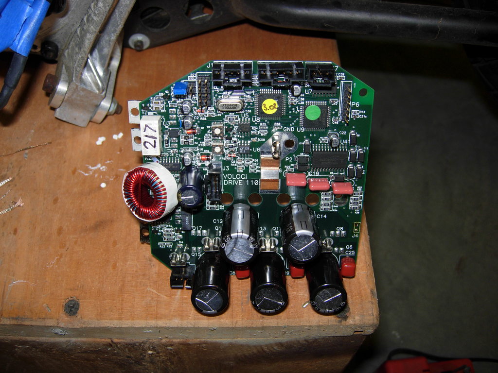
Inspect Transistors
The two rows of 6 black plastic rectangles are the power transistors (MOSFETs) that control the current going into the motor coils. (The other four big semiconductors are voltage regulators and whatnot; just leave them as-is). Gently bend the transistors up so they stick vertically out of the board instead of laying flat. Look at the label printed on the transistors. If they say "IRF1407" you are in luck -- you can just keep these transistors as-is. If they say "IRFZ48V" then you need to order 12 new IRF1407's, and replace the existing transitors. I didn't have to do this, so I won't provide instructions. But it should be similar to replacing the caps -- you de-solder the old ones, and solder in the new ones.
De-solder the bypass caps
1. Locate the 5 bypass capacitors -- these are the largish cylinders sticking 1" or so out of the board, near the transistors.
2. Turn the board over, and make sure you have located the pins where the bypass caps are soldered in.
3. Heat up your soldering iron, and de-solder each bypass cap. I used de-soldering braid to help remove the old solder. Remove each cap as you get it de-soldered. This was easier than I expected.

Solder in the new caps
1. Put a new cap into place. Figure out how long the leads need to be on the new cap, so they just barely poke out the bottom of the board, and trim the leads to that length.

2. Put the new cap in place. MAKE VERY SURE you have the polarity correct. The board is labeled with '+' where the positive lead of the cap should go. Looking at the bottom of the board, solder the leads into the holes.
3. Repeat for the other four caps. I found the soldering surprisingly easy, so don't be too intimidated.
Re-assembly
1. Re-attach the white wires. This was the hardest step for me. I did this by twisting and soldering on some longer wires to the existing wires, since they were so short and flimsy and hard to work with. I used heat-shrink tubing to cover the splice. Once I had longer wires, I soldered them back onto the board. I used too much heat when de-soldering, and did kind of a crappy job, but eventually got it together in one piece. To be extra sure, follow the traces on the board, and check with a multimeter to make sure the white wires have continuity with where they are going on the board.
2. Gently bend the transistors etc so they lay flat again. Locate the pink rubber gaskets for the semiconductors. ESSENTIAL TRICK: I stuck those gaskets back onto the semiconductors using a dab of dielectric grease (white stuff) that was still hanging around inside the controller housing. I had a heck of a time getting those gaskets to stay in place until I figured out to use the grease.
3. Screw the transistors back onto the bike. Don't tighten all the way until you have all 16 screws in, plus the 2 screws for the spacers. Then tighten gently but firmly.
4. Plug all the wires back in. Triple check your labels.
Test
The Voloci should now be functional, with the old battery pack. Give it a try, watching for malfunctions. You should initially see all five LEDs blink once and then stay on. No smoke should come out of anywhere. You should be able to turn the throttle to spin the rear wheel (which should be elevated so it doesn't go anywhere!)
Mine worked the first time. If anything went wrong with yours, good luck! I don't have any real advice, but I am interested to hear your story.
Connecting the 48V Battery
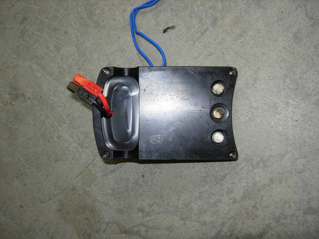
My initial strategy was to use the empty shell of my bad NiMH battery to connect to the contact bolts at the base of the existing battery compartment. This turned out to be a BAD IDEA, as I didn't adjust the bolts very well, and the middle bolt was arcing. I ended up melting the base of the old battery case to the point where it was not usable as an interface to the bike. (In the picture, you can see the blackened bolt, and a sort of growing crater in the plastic around it.)
I discovered a much better strategy: put Anderson Power Pole connectors on everything. I.e. the new battery, the old battery, the motor controller, and a jumper wire to help connect things that are otherwise too far apart. The Anderson connectors only come in one gender, but are cleverly keyed so you can't reverse the polarity.

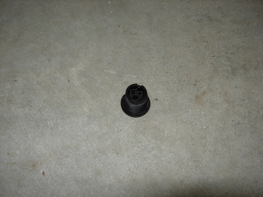
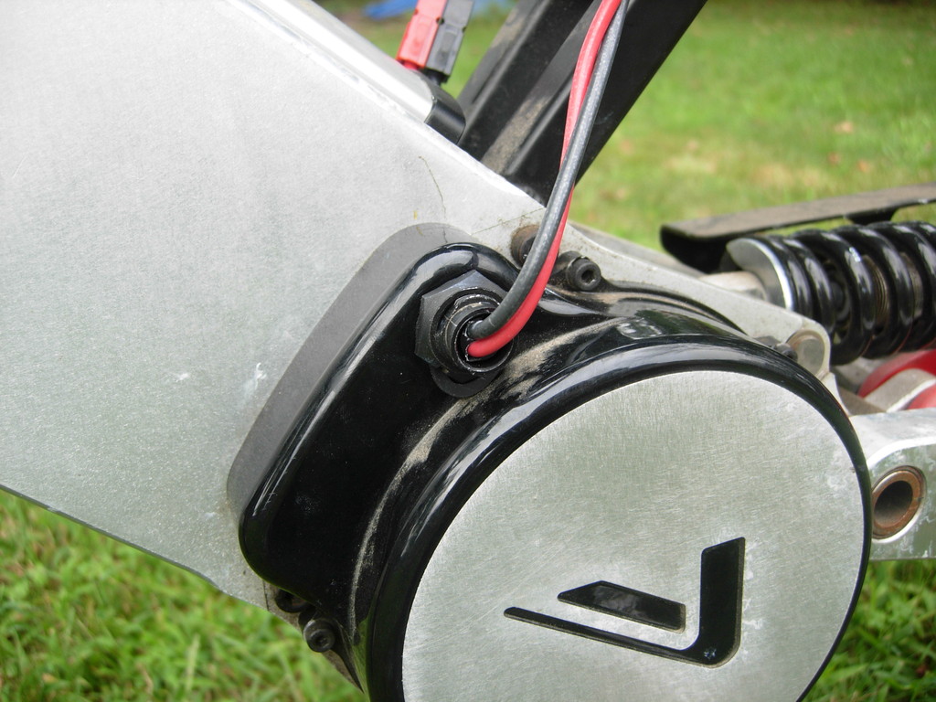
To get an Anderson connector into the motor controller, I unscrewed the plastic charging port, pulled out the three existing metal pins using pliers, and drilled out two of the resulting holes (using a 5/32 drill bit). The newly widened holes are perfect for running 12 gauge wire. I used a little tie-wrap around the wires on the inside, for ghetto strain-relief.
I spliced these two wires into the existing battery input wires. Even though you won't need the battery connector bolts anymore, DO NOT CUT THE WIRES running to the battery connector bolts, since those also run up into other parts of the bike, like the on-off switch! I made this mistake and had to jury-rig a solution, and that was a royal pain.
I covered the connector bolts with electrical tape. Now, the only way to power the bike should be via the new Anderson connector. I converted my remaining NiMH battery to use the Anderson connector by taking off the bottom plastic plate, unscrewing the connector bolts, drilling a new hole in the plastic plate to accomodate new wires, splicing the new wires to the old wires, and running the new wires out the new hole. If you do this, be careful to cover any exposed battery wires with tape while you are working, to avoid any unexpected shorts. Room is a bit tight inside the base of the battery so be economical with how you pack it all back together.
TRIPLE-CHECK the polarity of all your connectors! Getting this backwards will definitely fry stuff.
Mechanical Mounting
I rigged up a very rough method of mounting the new battery on the bike, between the seat and the front of the bike. It involves a piece of wood, some U-bolts, some angle brackets, a piece of rubber Welcome mat, and some nylon strapping. It's terrible and ugly, but all the parts came from the hardware store, and it has been adequate for testing. It also has the advantage that I can still carry the NiMH battery as a backup. I won't describe it in detail since you can surely come up with something better yourself. I do plan to improve my battery mount in the future with a proper box and a more secure bike attachment.

Results
The bike is fricking fast now! Comparatively speaking of course. The acceleration up to 25mph is very exciting, and it gets to 30mph in about 12 seconds. That's with me riding; I weigh ~250lbs so it should be even faster for most people. At full throttle, the bike comfortably maintains around 31-32mph even up slight inclines, and tops 35mph on a long flat or a slight downhill.
In terms of range: BIG IMPROVEMENT! I took a ride until full battery cutoff, and I went 14.13 miles. Full throttle most of the way, average speed 25.6mph, took about 34 minutes. The ambient temp was in the low 70's or so, and I didn't have any problem with controller overheating. I didn't notice any performance dip until about 0.5 mile from the end of the ride, when the speed sagged noticeably. The battery measured 50.8V a few minutes after cutoff.
Issues
There are two main problems that need to be resolved:
On a couple of hot days when I was testing, the controller shut off due to overheating. (Ambient temps in the mid to high 80's, I think.) What happens is, when the temperature of the controller heatsink tops 62C, the controller automatically reduces the throttle to a trickle, and flashes the battery gauge LEDs. When the temp drops down under 60C, the controller goes back to normal and you can use full power.
This has happened to me a couple of times now. I have been able to cruise along at a top speed of 18mph or so when in the over-temp condition (with extremely sluggish acceleration), and the temp will eventually come under limits and away I go. Or, just stop and wait for a few minutes.
By feeling around with my hand, the hottest part of the bike is at the bottom of the motor housing, on the edge of the big aluminum plate on the controller side (i.e. the part nearest to the MOSFETs). I'm very interested in some solution to the overtemp, perhaps with cooling fins around this area, or something like that. Another possibility is to go easy on the throttle when it's hot out.
The accessories don't work on a 48V supply. I.e. the horn, the turn signals, the headlight. They do work if I re-connect to the 36V battery, so it's not a blown a fuse.
These are pretty essential for safety, especially the turn signals, so I need to solve this, but I haven't had the time yet to figure out how the accessory circuits work.
I am also somewhat worried that I am abusing the battery by pulling so much power. I'm advised that at 50+ Volts, the Voloci motor could be pulling 50A, which is right near the rated maximum current of the battery (60A), and far above the max continuous rating (20A). The battery management electronics on the Ping will supposedly cut off current if the maximums are exceeded, but I have seen no sign of this yet.
There are two action items here: first, get a good ammeter in place; I'm eyeing the Watts Up, or the Cycle Analyst. Second, add a second battery in parallel with the first battery. This should be great for range as well.
Feedback
If you have a Voloci and try this, or have tried related modifications, I'd like to hear about it!
Suppliers and Parts
http://pingbattery.com makes the battery I used in this mod. They make other variations as well. Total cost with shipping was $582. My dealings with them were smooth and efficient. They took about 6 days from the time I ordered until they shipped the battery. It came via airmail from China, and it looks like it took about 2 or 3 days to reach my Post Office (where it sat for a few days until I picked it up). The battery comes with a charger, and so far everything has performed great.
http://digikey.com sells all kinds of electronic parts. I got the caps from them, and they should have the MOSFETs if you need them. They also sell solder, desoldering braid, heat-shrink tubing, yadda yadda yadda.
http://windsun.com sells Anderson Power Pole connectors and has some useful explanation of them.
http://powerwerx.com also sells Anderson Power Poles, as well as an affordable hand crimper for assembling them (the TRIcrimp).
http://batteryspace.com sells lots of different kinds of batteries, cells, and battery parts. Ping is more turn-key, but if you want to explore other battery options, batteryspace is very interesting.
References
Endless Sphere has forums with endless threads on e-bike and motorbike projects. Tons of good info in there, amid lots of chitchat.
|
voloci | 48V mod | 36V mod | Reflashing the Voloci controller |