"Powered" by Textweb
|
voloci | 48V mod | 36V mod | Reflashing the Voloci controller |
Reflashing the Voloci controller
2011-08-10
DISCLAIMER: THESE INSTRUCTIONS ARE PROVIDED AS-IS. USE AT YOUR OWN RISK. I TAKE NO RESPONSIBILITY FOR DAMAGE, INJURY OR DEATH THAT MAY RESULT.
The original Voloci has a problem where the microcontroller program stored in Flash memory can become corrupted semi-randomly. (I think there's some tiny chance of it happening every time the power is interrupted? Something like that.) Anyway, the problem may manifest as the motor not running smoothly, or running backwards, or not running at all. It seems like a mechanical or electrical problem but it's actually just software corruption.
Fortunately, it is possible to fix this problem by re-flashing the original program into the microcontroller. And, by programming the EEPROM on the microcontroller, it might make the problem less likely to recur (I'm not 100% sure about that part).
In any case, here are instructions for how to do this repair. It's esoteric but actually pretty easy, and it will be even easier for you if you find the right ready-made cable. I bet there are a bunch of Volocis out there gathering dust that could be fixed using these instructions!
Hardware
1. You will need a programmer for an Atmel AVR microcontroller. "Programmer" here meaning a little electronic device that plugs into the controller board to communicate with the Atmel chip. I bought an Atmel AVRISP mkII from Digikey for 30 or 40 bucks, also listed here on Atmel's site. The AVRISP mkII plugs into a computer via a USB port, and has a 6-pin serial cable to connect to the microcontroller.
There are other programmers out there which I'm sure would work just fine too, some of them very cheap or even homemade, but I got the AVRISP mkII because it's the standard, and it was reasonably priced and available.
2. If your programmer, like mine, only has a 6-pin serial cable, you will need a cable that goes from the 6-pin serial cable on the AVRISP mkII to the older 10-pin serial standard on the Voloci controller. These connectors are standard ribbon cables. The signals are functionally identical between the 10-pin and 6-pin standards; the 10-pin just has three extra ground pins and one completely unconnected pin. But the arrangement is different so you need a cable or adapter.
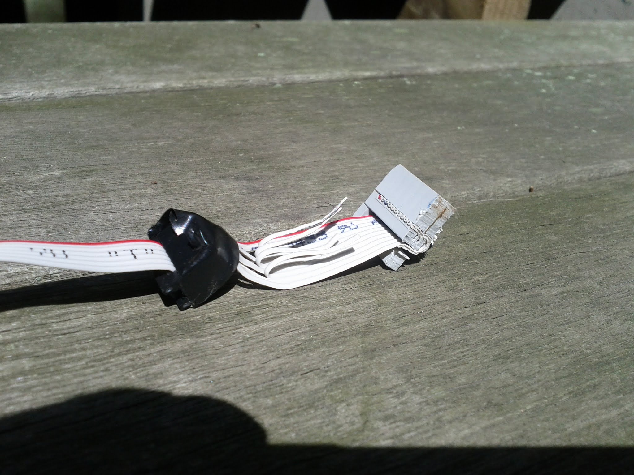
With a properly stocked electronics toolbox you can make one of these cables in like 10 minutes using AMP-Latch connectors or whatever. Or you can probably find a ready-made one online (this MIGHT be the right one). But I didn't have the right parts and I didn't want to wait so I improvised. I took an old IDE ribbon cable, cut the ribbon in half, peeled a group of 10 connectors back to the connector end, and hack-sawed off the first 5x2 rows of the connector on one end. You know it's a hack job when you use a hack saw!
Then I stripped the ends of the 6 necessary wires out of the 10 wires in the ribbon, and poked them into the correct holes on the 6-pin connector from the AVRISP mkII. I held the wires in place with a short piece of electrical tape.
I got the pin assignments from this cool page. But I will repeat them here in case of bit rot:
   These are the pinouts of the 6-pin and 10-pin ISP interface
   connectors.  From above, they look like this:

           1   2                       1    2
         +---+---+                   +---+---+
    MISO |[ ]|( )| +Vcc         MOSI |[ ]|( )| +Vcc
         +---+---+                   +---+---+
     SCK |( )|( )| MOSI         (NC) |( )|( )| Ground
         +---+---+                   +---+---+
   RESET |( )|( )| Ground      RESET |( )|( )| Ground
         +---+---+                   +---+---+
                                 SCK |( )|( )| Ground
                                     +---+---+
                                MISO |( )|( )| Ground
                                     +---+---+
My hack job only connected the pin-10 ground, and left pins 7, 5, and 3 unconnected. I triple-checked that I had the right wires going to the right holes, and it worked the first time.
Software
There is free open-source software for driving the AVRISP (and other programmers). I used AVRDUDE and it worked great. The laptop I had handy was a Macbook so I got AVRDUDE by installing MacAVR, which also includes a compiler toolchain and so on. (I haven't yet tried to write any new code for the Voloci so for now I have only used AVRDUDE to program the stock binary.)
AVRDUDE also works on Windows and Linux; it should be easy to find a download.
I obtained a copy of the stock Voloci firmware, version 3.12; you can download it here in binary format. This is the data you will copy into the bike's microcontroller.
Procedure
1. Plug your AVRISP mkII or whatever programmer you have into your computer, via USB.
2. Identify the serial number of your programmer. On a Mac you can do this by entering the command:
system_profiler SPUSBDataType
Look for the entry that corresponds to your programmer and jot down the last few digits of the serial number. You will use this to tell AVRDUDE which USB device your programmer is.
On Linux you can use lsusb to get this info. On Windows I'm sure there is something but I don't know off the top of my head.
To check that you have AVRDUDE installed and that you can talk to the programmer, you can try a command like this:
avrdude -p 8535 -n -c avrispmkII -P usb:<serial_number>
The -n parameter tells it not to actually do anything, but when you run this, AVRDUDE will address the programmer and the LEDs on an AVRISP mkII will flash. Then you'll get an error message because nothing is actually plugged into the programmer yet. That comes later.
3. Make sure your Voloci battery is charged up.
4. Turn off the Voloci and disconnect the battery (remove the battery or remove the fuse).
5. Remove the controller cover (unbolt the 5 small hex bolts on the left-hand side of the motor assembly). Don't lose the o-ring that seals the cover to the frame.
6. Reconnect the battery power (replace battery or fuse). Turn the bike on.
7. With the bike switched on, remove the hall sensor connector via J1.
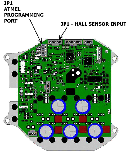
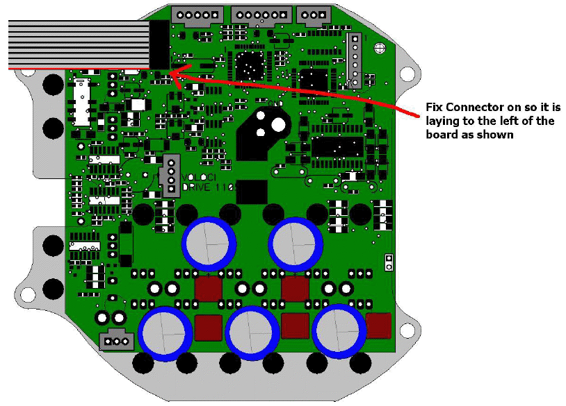
8. Connect the 10-pin controller cable to the controller board.
9. Disconnect at least 2 out of the 3 motor wires (thick black wires plugged into the lower part of the controller board).
10. Sanity-check the computer-to-controller connection by running this command on the computer:
avrdude -p 8535 -c avrispmkII -P usb:79004 -U flash:r:tmp.hex:h
That command should read the current contents of the Voloci microcontroller Flash memory into a file on your computer named "tmp.hex". AVRDUDE should report success, and you can also look in that file to see if you got something. If not, double check your connections, and also make sure the bike is still powered up.
11. Program the stock Voloci firmware into your bike's controller Flash, like so:
avrdude -p 8535 -c avrispmkII -P usb:<serial_number> -U flash:w:voloci_firmware_rev312.bin:r
(Replace <serial_number> with the value you obtained earlier.)
12. Program the stock Voloci firmware AGAIN, but now into your bike's controller EEPROM:
avrdude -p 8535 -c avrispmkII -P usb:<serial_number> -U eeprom:w:voloci_firmware_rev312.bin:r
13. Disconnect the bike battery.
14. Unplug the programmer cable from the bike, re-connect the hall-effect plug, and re-connect the motor wires. Bolt the cover back on.
15. Re-connect the battery. Check to see that the motor works. Check the brakes, and go for a test ride!
Resources
Here is the original document from Nova Cruz explaining the programming procedure.
Here is a .zip file containing the original controller source code and compiled firmware rev312. Someday I'd like to make modifications but for now the stock firmware is fine.
Feedback
If you have a Voloci and try this, or have tried related modifications, I'd like to hear about it!
|
voloci | 48V mod | 36V mod | Reflashing the Voloci controller |